DL Test Model
The Cell ID is assigned based on the current carrier index, i.e. Carrier 1 use Cell ID 1, Carrier 2 use Cell ID 2.
Bandwidth
Choices:
Downlink: Based on the Table 5.3.2-1 and 5.3.2-2 in 38.104
Uplink: Based on the Table 5.3.2-1 in 38.101-1 and 38.101-2
Selects the bandwidth configuration for the carrier.
Numerology
Selects the numerology of the test model. The choices are related to the selected bandwidth.
Duplex Type
Choices: TDD | FDD
Default: TDD
Selects the duplex type of the test model.
Transmission Periodicity
Sets the periodicity of DL-UL pattern. The choices are related to numerology.
Read-only.
Number of Downlink Slots
Sets the number of consecutive full DL slots at the beginning of each DL-UL pattern. The range is related to the numerology and slot configuration period.
Read-only.
Number of Downlink Symbols
Range: 0 ~ 14 for Normal CP; 0 ~ 12 for Extended CP
Sets the number of consecutive DL symbols in the beginning of the slot following the last full DL slot.
Read-only.
Number of Uplink Slots
Sets the number of consecutive full UL slots at the end of each DL-UL pattern. The range is related to the numerology and slot configuration period.
Read-only.
Number of Uplink Symbols
Range: 0 ~ 14 for Normal CP; 0 ~ 12 for Extended CP
Sets the number of consecutive UL symbols in the end of the slot preceding the first full UL slot.
Read-only.
Number of Special Slots
Displays the number of special slots.
Read-only.
TDD Slot Allocation
Displays the TDD slot allocation for one period.
Read-only.
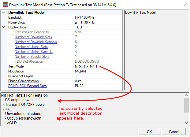
Test Model
Choices: NR-FR1-TM1.1 | NR-FR1-TM1.2 | NR-FR1-TM2 | NR-FR1-TM2a | NR-FR1-TM3.1 | NR-FR1-TM3.1a | NR-FR1-TM3.2 | NR-FR1-TM3.3 | NR-FR2-TM1.1 | NR-FR2-TM2 | NR-FR2-TM2a | NR-FR2-TM3.1 | NR-FR2-TM3.1a
Default: NR-FR1-TM1.1
Selects the Test Model to configure. The choices are defined in the section 4.9.2 of 38.141. A description of the currently selected test model appears in the hint window directly below.
Modulation
Choices: QPSK | 16QAM | 64QAM
Default: 64QAM
Set the Modulation Type for NR-FR2-TM2 or NR-FR2-TM3.1.
Number of Layers
Choices: 1 | 2
Sets the Number of Layers (Rank) for Test Model 1.1, two layers MIMO transmission is used for TAE requirement, single layer is used for others.
Phase Compensation
For waveform playback mode:
Choices: Auto | Auto (Real-time) | Manual | Manual (Real-time) | Off
For real-time uplink mode:
Choices: Auto | Manual | Off
Default: Auto
Sets the phase compensation mode on baseband signal before upconversion.
Auto | Auto (Real-time): Use the RF frequency from the instrument node.
Manual | Manual (Real-time): Enter the RF frequency manually.
Off: Disable phase compensation on baseband signal.
(Real-time) means the phase compensation is done using FPGA inside the instrument.
DCI/DLSCH Payload Data
Choices: PN9 | PN23
Default: PN23
Select the PN type for Downlink Test Model.